French Renault FT-17 Build
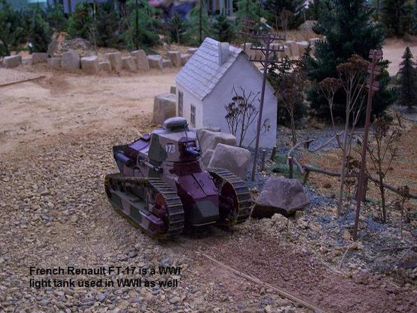
The FT-17 is a light tank that was used in WWI and WWII by many countries. This is an article on a coustom built full option (FO) RC tank with IR battlesystem.
Model Prep
The inspiration for this build came from a 15th/16th scale metalized paperboard static model acquired from Poland and the fact there just are no WWI radio-controlled subjects in this scale that can electronically battle other tanks. Modeling a radio-controlled World War I French tank would be a great challenge and be quite unique. In order to convert to RC use, the build uses major components from the Norscot Caterpillar 22, Heng Long Pershing tank and Tamiya electronics. Space planning and management of components in this rather small tank became an overwhelming consideration during the project. Many of the components were miniaturized.
It took two donor 16th scale Norscot Caterpillar 22 die cast models to supply enough track for one complete model . The track system being the most difficult challenge of tank model design when scratch building, was substituted to eliminate much work and expense in construction. Although not quite accurate in that it takes exactly two links to make one full FT-17 track link, it is otherwise a very good approximation for the real track. The sprocket was used albeit refashioned to insure proper tracking. All the individual links were drilled to accept nails as track pins for extra track strength and to provide more positive engagement for the sprocket teeth. The engine crank handle was also reused.
It took two donor 16th scale Norscot Caterpillar 22 die cast models to supply enough track for one complete model . The track system being the most difficult challenge of tank model design when scratch building, was substituted to eliminate much work and expense in construction. Although not quite accurate in that it takes exactly two links to make one full FT-17 track link, it is otherwise a very good approximation for the real track. The sprocket was used albeit refashioned to insure proper tracking. All the individual links were drilled to accept nails as track pins for extra track strength and to provide more positive engagement for the sprocket teeth. The engine crank handle was also reused.
The Tracks, Gearboxes and Electronics
The drive gearboxes, turret rotation and speaker were taken for reuse from the Heng Long “Snow Leopard”. Custom primary gear reduction was fabricated and installed on the drive gearboxes to increase torque and better approximate the actual speed of the vehicle. The turret rotation gearbox was modified for a keyed receptor for the turret.
Tamiya DMD and MF unit were used as the basis for the electronics for full option capability. The battle system was also installed for infra red battles. This electronics system was chosen for its proven robustness and option compatibility.
Two donor tractors were used to complete a full track set including sprockets. Each track link was drilled and pinned with a nail for strength and to engage the sprocket teeth better.
Bottom Plate
The bottom plate and cross supports were fabricated from 1/8th inch aluminum stock sheet and C-channel. Gearboxes were mounted as close together as possible because of the narrow vehicle. The height of the vehicle allows plenty of room for high profile gearboxes.
Gearbox and Motors
The motors were changed out from the stock 380 to a smaller format motor for two reasons.
First reason, physically the stock 380 can was too long not allowing the clearance needed to keep the narrow nature of the vehicle. And second, electronically smaller motors would be more efficient. A large powerful motor was not necessary as the smaller motor would be compensated with a custom 2x gear reduction fabricated on the first stage so torque would be maintained. Smaller, more efficient motors will have less current draw thereby eliminating the need for a large stick battery. A small format 2/3A battery became necessary because the standard sub-C stick would not fit in the confined interior space.
The custom gear reduction also helps in that the actual speed of the actual vehicle was about 5mph, quite slow by today’s RC gearbox ratios, so adding a reduction would only get closer to the real scale value. The stock nylon gears were maintained in the gearboxes. Metal gears were not needed as the model is quite light by RC tank standards and the stress will be low coupled with the low speeds it will be performing. The nylon gears will also be quieter and reduce weight. Custom gear reductions were made from donor gears, shafts and pinions mounted on custom aluminum sub-plates attached to the actual gearbox with micro bolts. The speaker box was installed in the space between the gearboxes. White Lithium grease was added to the gears.
Sprocket
The sprocket was remade from the donor Caterpillar in which aluminum solid plate was added on either side with a key for the axel flat.
Paperboard shell on Chassis
The paperboard static model is shown next to the skeleton of the new construction fabricated from aluminum stock. The new construction has the drive gearboxes, speaker, sprockets and cross arm in preparation for the running gear to be installed.
Bogie Construction
Work began on the running gear. Below is the first of two bogies per side, one five wheel and the other four wheel. Normally the bogiewould be sprung but in preference of simple construction, the bogies were configured for rocker arm suspension similar to the Bandai models. The wheels are nylon spacers for the inner and grommets for the outer portion. Again this was an approximation of the real wheel in order to simplify construction.
Bogie Track Guides
The bogie is shown fitted as the track guide. The tracks were kept representatively simple as fusing links for the sake of correct pad length was deemed too involved a process.
Idler Parts
Parts of the massive idler wheel and tension adjuster mechanism are shown below. Again this design was simplified for construction as many small and otherwise adjustable mechanisms were rather complex. The rigors of RC would likely break such components so a stationary representation was fabricated. The idler wheel used doorknob wall plate protectors.
Running Gear with Tracks
The working running gear assembly shows the return rollers made from nylon spacers and brass bar, idler, road wheels and sprocket. It is noted that the return roller arm is sprung to help maintain positive tension with the track to avoid throwing a track in hard turns. The two sets of 5 and 4 road wheel bogies each have an articulating rocking arm.
The running gear with the track installed is tensioned by the sprung return roller arm. The bogies have rocker arm pivot points. The idler mechanisms are stationary.
The running gear with the track installed is tensioned by the sprung return roller arm. The bogies have rocker arm pivot points. The idler mechanisms are stationary.
Detailing
Wherever possible the static pieces from the metalized paperboard model were used to add detail and finish to the running parts since modeling detail is not my specialty. Detailing begins to cover up the frame with finish pieces from the paperboard model. With such expertly modeled details, there was no use in letting it go to waste!
Gearbox Protection
For added protection the gearboxes were sealed using metallic tape. This prevents dust, dirt and wires becoming caught in the gears and wearing prematurely. It also prevents grease from spattering all over the inside of the model when running.
Antenna
The radio antenna was conveniently disguised as the large single exterior muffler. A helical coil wrapped around a piece of hot glue stick worked perfectly in achieving the exact wire length for optimal reception
The antenna disguised as the muffler was installed on the right toward the rear of the vehicle.
The antenna disguised as the muffler was installed on the right toward the rear of the vehicle.
Electronics Arangement
The DMD and MF units are stacked and the ON/OFF switch was attached beneath the units in the front accessible via front driver’s hatches
Overhead view shows a tightly packed electronics and gearbox workings of the RC model. The DMD/MF are stacked on bottom with the turret rotation gearbox mounted on top with double sided tape. The rotation assembly uses a similar rotation method as the early Tamiya King Tiger model. The covered drive gearboxes are to the left with the speaker box in between. The signal lines feed from the DMD to the rear of the vehicle where the radio receiver is attached with connection to the helical antenna mounted on the side.
Notice that the wire management is kept orderly and tight as possible. Proper space management is essential for reliable operation and proper access to controls and indicators. Most of the wires are routed bundled under and alongside equipment, which also keeps them from becoming twisted and interfering with moving parts.
Trench Tail Device
Making of the tail piece, which aids in trench crossing, was accomplished by adding aluminum plate underneath for the spade portion of the tail piece and adding a hinge and support bolt for mounting to the end of the vehicle.
Turret Rotation
The turret sets on top of the rotation gearbox with sleeved tubes vertically engaging the bolt stub ups. The turret was small but can fit the needed devices with proper planning. The devices and functions that need to be located in the turret were the battle system, elevation servo, IR LED and machine gun LED. Recoil of the main gun was omitted. Using a sub-micro servo for the gun elevation saved much space. Size is shown compared to car keys!
The servo had to be disassembled and hacked for the DMD interface. The logic circuit and potentiometer were discarded since an analog signal was used. The leads of the motor will directly connect to the DMD rotation wires. In this case a diode pair bridge was added to slow the motor slightly for more realistic elevation speed.
The servo had to be disassembled and hacked for the DMD interface. The logic circuit and potentiometer were discarded since an analog signal was used. The leads of the motor will directly connect to the DMD rotation wires. In this case a diode pair bridge was added to slow the motor slightly for more realistic elevation speed.
|
|
Battle System
The battle unit is also added to the turret with a custom mounting plate attached to the plug. The assembled unit is bolted to the underside of the turret commander hatch opening and adjusted for correct height.
|
|
Paint and Weathering
The original modelers paint and weathering techniques were quite good but the old and dilapidated look was just a bit too much. The vehicle was repainted in similar color and pattern with less aging and wear evident. The shell also shows the cutouts on the sides to accommodate the gearbox sides. The gearbox sides, because of the narrow nature of the vehicle, were made to be joined with the shell cutouts.
Receiver Location and Turret Guide
The rear tail piece is attached and also the small format receiver mount is shown with its connection to the helical antenna (muffler). Also present is the manual engine crank on the back plate of the vehicle salvaged from the Caterpillar model.
The removable turret is tested on the rotation gearbox. A turret ring guide is present that seats into the hull opening.
The removable turret is tested on the rotation gearbox. A turret ring guide is present that seats into the hull opening.
|
|
Battery and Final Assembly
For the battery, a small format 2/3A high drain type battery was used because of space constraints. The stick was separated and reconfigured in saddle-pack style to fit in the remaining space inside the vehicle. Batteries were fitted on top of the gearboxes with three cells on either side of the speaker. The battery cable is accessible via the engine hatch for charging. Deans connectors were used to maximize space and provide better connections between the DMD/MF and battery.
Access to the battery for charging was made via the engine hatches.
Likewise the ON/OFF switch was made accessible via the driver’s hatches.
Access to the battery for charging was made via the engine hatches.
Likewise the ON/OFF switch was made accessible via the driver’s hatches.
|
|
